
EN10219 Steel Pipe Container Loading Config for FCL Buyers
Optimize your Steel Pipe Container Loading Configuration to prevent transit damage and reduce freight costs for EN10219 hollow sections. Learn how nesting strategies, proper dunnage, and weight distribution balance volume utilization with structural stability. Avoid common loading pitfalls that lead to costly claims and inefficient space usage in FCL shipments.
- Published
- Updated
- Read time
- 8 min
- Comments
- 0

EN10219 Steel Pipe Container Loading Config for FCL Buyers
Most buyers assume maximizing weight saves money; truly, optimizing volume utilization often yields better cost-per-unit efficiency for hollow sections.
Efficient container loading for steel pipes requires balancing theoretical volume with physical constraints like wall thickness tolerances and stacking stability to prevent transit damage and optimize freight costs. A proper Steel Pipe Container Loading Configuration accounts for the gap between nominal dimensions and actual manufactured sizes, ensuring that dunnage placement prevents point-load deformation while maximizing the use of available cubic space. Without this balance, shippers risk paying for air or facing costly claims for crushed bottom layers.
I still remember the silence in the warehouse when we opened the first few bundles of square hollow sections destined for a German contractor. The outer wraps were intact, but the inner tubes in the lowest tier showed slight ovalization. We had calculated the load based on perfect geometric stacking, ignoring the cumulative effect of wall thickness tolerance and the micro-movements caused by ocean vibration. That claim cost more than the profit margin on the entire order. Since then, I have learned that a robust Steel Pipe Container Loading Configuration is not just about fitting as many tons as possible into a box; it is about engineering a stable structure that survives the dynamic forces of maritime transport.
Transitioning from quality control on the production line to managing export logistics revealed how often theoretical calculations fail in practice. The following insights break down why standard plans fall short and how to build a configuration that protects both the cargo and your bottom line.
Why Do Standard Loading Plans Fail for Steel Pipes?
Theoretical calculations ignore manufacturing tolerances and transit dynamics, leading to unexpected voids or structural failure.
Many procurement teams rely on simple volume division: container volume divided by pipe bundle volume. This approach assumes pipes are perfect cylinders or rectangles with zero deviation. In reality, EN10219 standards allow for specific tolerances in external dimensions and wall thickness [NEED_CITE: EN10219 dimensional tolerance specifications]. When you stack hundreds of tubes, these minor deviations accumulate, creating gaps that reduce loadable quantity or, worse, create unstable stacking points.
Consider the case of a shipment to Southeast Asia involving heavy-wall pipes. The loading plan was optimized for weight, filling the 20-foot container to its maximum payload capacity. However, the distribution did not account for the floor strength limits of the container. The concentrated weight of the steel bundles created point loads that exceeded the local floor bearing capacity, causing the container floor to bow slightly during crane lifting. While the cargo arrived, the container was rejected by the terminal for structural integrity issues, delaying clearance.
A common mistake is assuming standard stacking is safe without specific dunnage layers. Bottom-layer pipes often suffer micro-deformation from the weight of upper layers during ocean vibration if the contact area is not properly distributed. This is where a professional Steel Pipe Container Loading Configuration becomes critical. It moves beyond simple arithmetic to consider the physical behavior of steel under stress.
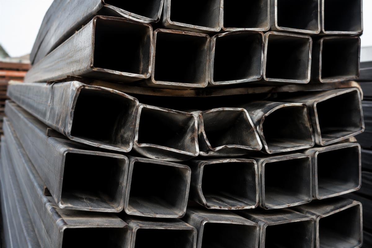
The failure usually stems from two sources: ignoring the “air” created by tolerance stacks and underestimating the dynamic forces at sea. Ships roll and pitch, causing cargo to shift. If the loading plan does not include adequate securing and friction management, even a perfectly weighted container can experience internal movement that damages the product.
How to Calculate Optimal Stowage for SHS and RHS?
Nesting strategies and gap management significantly increase loadable quantity compared to simple side-by-side stacking.
For Square Hollow Sections (SHS) and Rectangular Hollow Sections (RHS), the shape allows for nesting, which can dramatically improve space utilization. However, nesting is not always straightforward. Mixing sizes requires careful planning to ensure that smaller tubes fit securely inside larger ones without causing distortion or making unloading difficult at the destination.
A Middle East distributor once faced a dilemma with a mixed-size shipment. They initially planned to load varying RHS dimensions side-by-side, which left significant unused vertical space. By switching to a nested loading strategy for compatible sizes and using side-by-side placement only for non-nestable dimensions, they increased the total linear meters loaded by a noticeable margin. The key was calculating the effective stowage factor for each combination rather than treating each size in isolation.
| Loading Strategy | Space Utilization | Stability Risk | Unloading Complexity |
|---|---|---|---|
| Side-by-Side Only | Low to Moderate | Low | Low |
| Full Nesting | High | Moderate (if tight) | High |
| Hybrid (Nested + Blocked) | High | Low | Moderate |
The stowage factor calculation for SHS/RHS differs from seamless pipes because of the flat surfaces. Flat surfaces provide better contact areas for strapping but can also transmit shock more directly if not cushioned. When designing a Steel Pipe Container Loading Configuration, it is essential to simulate the load. At Xin Jiyuan, we use pre-shipment loading simulation services for custom non-standard sizes to ensure maximum container utilization before the cargo even reaches the dock. This step identifies potential clashes or inefficient gaps that manual calculation might miss.
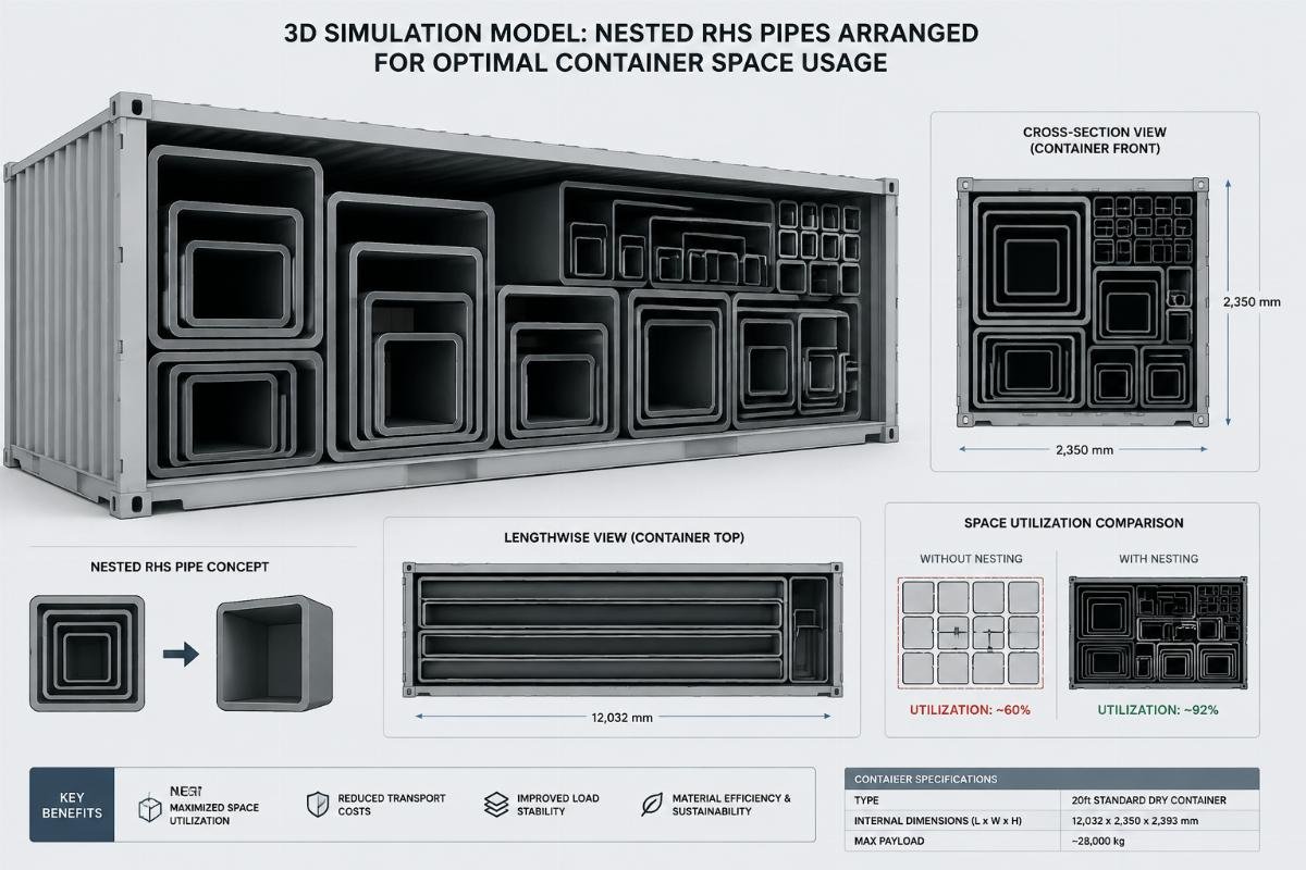
Another critical aspect is the orientation of rectangular sections. Loading them on their wider face provides a lower center of gravity and better stability, but loading them on their narrower edge might allow for tighter nesting in certain combinations. The choice depends on the specific dimensions and the need for cross-bracing with other cargo types.
What Are the Critical Dunnage and Securing Requirements?
Proper timber placement prevents point-load deformation and shifting during transit.
Dunnage is not just filler; it is a structural component of the load. The specification of timber—its thickness, width, and spacing—directly impacts the safety of the steel pipes. Thin or widely spaced dunnage fails to distribute the weight of upper layers, leading to the ovalization of bottom tubes. Conversely, overly thick dunnage wastes valuable vertical space.
International Maritime Organization (IMO) guidelines emphasize the importance of securing cargo to prevent movement [NEED_CITE: IMO CSS Code guidelines for steel cargo]. For steel pipes, this means using high-tension strapping combined with anti-slip measures. Rubber mats or specialized friction sheets placed between layers of steel and between steel and dunnage can significantly reduce the required strapping tension and prevent slippage.
A European buyer once reported damage to galvanized pipes due to direct contact with untreated timber. The moisture in the wood reacted with the zinc coating, causing white rust spots. This highlights that dunnage material selection is part of the Steel Pipe Container Loading Configuration. Using kiln-dried timber or placing plastic separators between the wood and steel can prevent such chemical reactions.

Securing methods must also account for the smooth surface of galvanized or painted pipes. Standard steel-to-steel friction is low, and paint can act as a lubricant. Therefore, relying solely on friction is risky. Strapping must be applied with consistent tension, and edge protectors should be used to prevent the straps from cutting into the pipe walls or damaging the coating. The pattern of strapping—whether horizontal, vertical, or diagonal—should be designed to lock the bundles together into a single rigid unit.
How to Balance Weight and Volume in FCL Shipments?
Aligning cargo weight with container floor strength avoids structural risks and optimizes freight costs.
There is a persistent myth that filling a container to its maximum weight limit is always the most economical approach. For dense materials like steel plates, this is true. However, for hollow sections like EN10219 pipes, volume often becomes the limiting factor before weight. A 40-foot high-cube container might reach its volumetric capacity with light-wall tubes long before it hits the 26-ton weight limit.
In such cases, focusing on weight optimization leads to wasted freight costs because you are paying for unused weight capacity. Instead, the goal should be to maximize the number of units per container, which lowers the shipping cost per piece. This requires a Steel Pipe Container Loading Configuration that prioritizes tight packing and minimal void space.
Conversely, for heavy-wall structural steel, weight distribution is paramount. Concentrating too much weight in one area of the container floor can cause structural failure during handling. The load must be spread evenly across the floor beams. This often means breaking large bundles into smaller, distributed loads or using spreader bars if mechanical handling is involved at the destination.

Balancing these factors requires a holistic view of the supply chain. It involves understanding the handling capabilities at both the loading and discharge ports. If the destination port lacks heavy-lift cranes, oversized heavy bundles may incur additional surcharges or delays. Therefore, the optimal configuration is not just about what fits in the container, but what can be efficiently handled throughout the journey.
Conclusion
Optimizing container loading for steel pipes is a balance of physics, standards, and practical experience.
A well-executed Steel Pipe Container Loading Configuration prevents damage, reduces freight costs per unit, and ensures smooth customs clearance. By accounting for manufacturing tolerances, using appropriate dunnage, and balancing weight with volume, buyers can avoid the common pitfalls that lead to claims and delays. The focus must shift from simple weight maximization to intelligent space utilization and structural stability.
Share this article
- LinkedIn -- share "EN10219 Steel Pipe Container Loading Config for FCL Buyers" on LinkedIn
- X -- share "EN10219 Steel Pipe Container Loading Config for FCL Buyers" on X
- Facebook -- share "EN10219 Steel Pipe Container Loading Config for FCL Buyers" on Facebook
- WhatsApp -- share "EN10219 Steel Pipe Container Loading Config for FCL Buyers" on WhatsApp
- Email -- share "EN10219 Steel Pipe Container Loading Config for FCL Buyers" on Email

Written by
author
Editor covering global sourcing, supplier verification, and industrial product knowledge. Content is compiled from manufacturer specifications, industry standards, and hands-on experience with international B2B buyers. Every article is fact-checked before publishing to help procurement professionals make informed decisions.
All posts by author

